
Suzhou days Lai He Automation Technology Co., Ltd.
Contact: Manager Song
Mobile: 13382502797
Tel: 0512-65820216
Fax: 0512-65893517
E-mail: Talach @ tianlaihe. Com
Website: www.tianlaihe.com
Address: North Road, Suzhou High-tech Zone 505
1) title bar: located in the lower right corner of the figure, the title bar generally fill in part name, material, quantity, pattern ratio, code and pattern of responsibility
Signed and unit name and other people. The direction of the title bar should be the same as the direction of the view.
2) a group of graphics: the structure used to express the shape of parts, you can use the view, section, section, the provisions of the simplified method of painting and simplified method of expression
expression.
3) Necessary dimensions: reflect the size of each part of the structure and the mutual positional relationship, to meet the requirements of parts manufacturing and testing.
4) Technical requirements: given parts surface roughness, dimensional tolerances, shape and position tolerance and material heat treatment and surface treatment requirements
.
Two. View
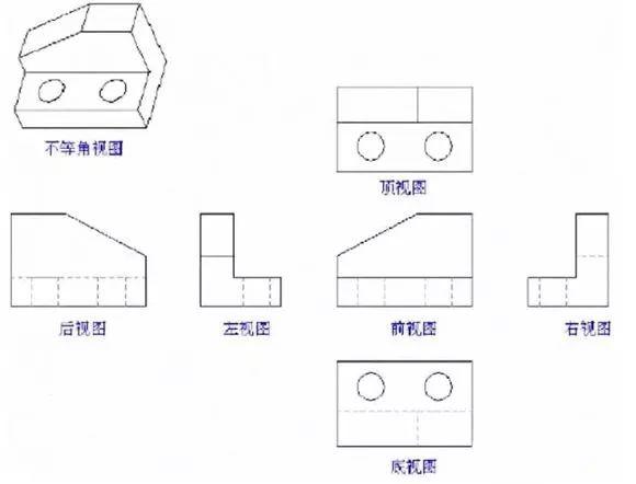
Basic view: View of the object projected onto 6 basic projection surfaces (the object is projected in the center of the cube in 6 directions up, down)
Three
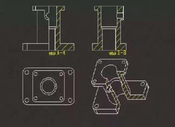
Full section view: cut with
The cutaway view of the cut object is called a full cut test:
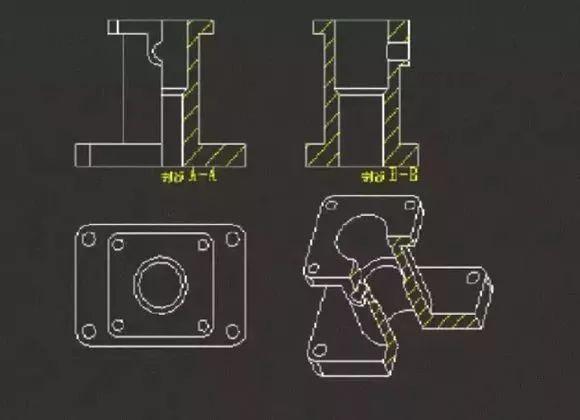
Half-sectioned view: When the object has a symmetrical plane, projected onto the projection plane perpendicular to the plane of symmetry can be taken as the boundary of the center line
, One half into a cross-sectional view, the other half into a view, known as half cross-sectional view:
Four. Dimensions and labeling
1, the size of the classification
1) The basic size: Through its application, the deviation can be calculated under the size of the limit size.
2) Actual size: the size obtained by the measurement.
3) limit size: one size allows the two extremes, the largest of which is called the maximum limit size; the smaller one is called the minimum limit
size.
4) size deviation: the maximum limit size minus the basic size of the resulting algebra is called the upper deviation; minimum limit size minus the basic size of the income
Algebra is called the next deviation. The upper and lower deviations are collectively referred to as the limit deviation, the deviation can be positive or negative.
5) dimensional tolerances: referred to as the tolerance maximum limit minus the size of the minimum limit of the difference, which is allowed to change the size. Dimension tolerance forever
Positive.
6) Neutral line: In the limit and mated figure, a line representing the basic dimensions, on the basis of which the deviations and tolerances are determined.
7) Standard Tolerance: Any tolerance specified in Limit and Fit. National standards, for a certain basic size, the standard public
The difference is a total of 20 tolerance levels.
Tolerance is divided into CT, IT, JT 3 series of standards. CT series for the casting tolerance standards, IT is the ISO international tolerances, JT for the Chinese machinery
Department size tolerances
Different product tolerance levels. The higher the level, the higher the technical requirements of production, the higher the cost.
8) The basic deviation: In the limit and cooperation system, to determine the tolerance zone relative to the zero line position that deviation, usually close to the zero line that partial
difference. The national standard specifies the basic deviation codes Latin letters, capital letters indicate holes, lowercase letters represent the axis, the hole and the axis of each
A basic size section specifies 28 basic deviations.
3, the size of the label
Size basis
Dimensional reference is the reference dimension positioning dimensions, the size of the benchmark is generally divided into the design basis (design time to determine the location of the part structure) and technology base
Standard (used to locate manufacturing, processing and testing).
Size benchmarks are divided into the main benchmarks and auxiliary benchmarks. Generally in the long, wide, high three directions to choose a design basis for the main benchmark, they
Determine the main dimensions of the part, the main dimensions from the main benchmark directly out. The rest of the size bases except for the primary basis are secondary
quasi.
V. Tolerance and cooperation
1, tolerance
In order to ensure the interchangeability of parts, the design of the use of parts according to the requirements of the allowable size of the change, known as the dimensional tolerances, referred to as
tolerance. The smaller the value of the tolerance, that is, the smaller the variation range of the allowable error, the harder it is to process.
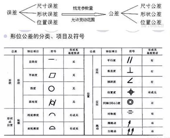
2, the shape and position tolerance (referred to as the form of position tolerance) concept
1) machined parts surface, not only the size of the error, but also produce shape and position error. These errors not only reduce the fine parts
Degree, but also affect the use of performance. Therefore, the national standard specifies the parts of the surface shape and position tolerances, referred to as the position tolerance.
2) Dimension Tolerance Note on part drawing
Marked in the part drawing dimensional tolerance commonly used mark the limit deviation value, as shown in the figure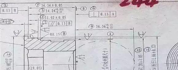
3) The requirements for the tolerances of box-shaped spaces are given in the box, which consists of two or more lattices. The contents of the box from left to right fill in the following order
WRITE: Tolerance sign, tolerance value, one or more alphabets to indicate the baseline element or baseline system, if required.
4) measured elements
Connect the element under test to one end of the tolerance frame with a guide with an arrow pointing in the direction of the width or diameter of the tolerance band. Means
Lead arrow refers to the site may have:
(1) When the measured element is the whole axis or the common center plane, the pointing arrow may directly refer to the axis or the center line, as shown in the figure on the left.
(2) When the measured element is the axis, the center of the ball or the center plane, the index line arrow should be aligned with the dimension line of the element, as shown in the following figure.
(3) When the element to be tested is a line or surface, the indexed arrow shall refer to the contour of the element or its lead-out and shall clearly correspond to the dimension line
Staggered, as shown below right
5) Benchmarking elements
Connect the reference element to the other end of the tolerance grid with the reference line with the reference symbol, as shown in the figure on the left.
(1) When the reference element is a prime line or surface, the reference symbol shall be close to the outline or lead of the element and shall be clearly marked with the dimension line
The arrow is staggered, as shown below left.

2) When the datum element is the axis, sphere center or center plane, the datum symbol should be aligned with the dimension line arrow of the element, as shown in the following figure.
(3) When the reference element is an integral axis or a common center plane, the reference symbol may be directly marked on the common axis (or the common center line)
Right below.
4, the position error and tolerance
Position error is divided into directional error, positioning error, beating error, the corresponding tolerances are directional tolerance, positioning tolerance, beating tolerance:

VI. Surface roughness
1, the concept of surface roughness
Surface roughness is a micro-geometry error, refers to the surface of the part with a small pitch and the valley composed of micro-geometry
Characteristics, assessment of the size of the surface roughness parameters.
1) Ra: Outline arithmetic mean deviation
2) Ry: Ten micro-level unevenness height
3) Rz: maximum outline height
Commonly used height parameter Ra, in the surface roughness code marking can also be omitted Ra. Such as the use of the other two evaluation parameters, it must be noted
Rz or Ry
Ra is generally measured with an electric profiler.
Because of the more intuitive concept of Ra, the amount of information reflecting the outline of the more widely used.
Ra commonly used parameter range of 0.025 ~ 6.3μm.
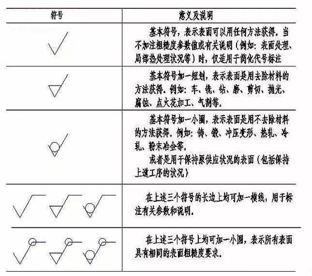
2, surface roughness symbol and its significance
That with the processing of the surface, the Ra value of not more than 3.2um, due to the recommended priority to use the parameters Ra, so "Ra" do not note. This is the most commonly used symbol
.
Said with the processing of the surface, the Ra value must be between 3.2-6.3 um, generally rarely use such a label. Generally only provides the maximum allowable value.
Said the surface is not removed material method, that is, non-processing surface, such as casting forging surface, the Ra value of not more than 1.6um.
Surface obtained by any method, Ra value of not more than 25
Surface roughness generation [symbol] Number method
612/5000Biǎomiàn cūcāo dù biāozhù
1) biǎomiàn cūcāo dù dài [fú] hào yīng zhù zài túyàng de lúnkuò xiàn, chǐcùn jièxiàn huò qí yáncháng xiàn shàng, bìyào shí kě zhù zài zhǐyǐn xiàn shàng. Fúhào de
jiānduān bìxū cóng cáiliào wài zhǐxiàng gāi biǎomiàn.
2) Zài tóngyī túyàng shàng, měi yī biǎomiàn yībān zhǐ biāozhù yīcì dàihào huò fúhào. Wèi biànyú kàn tú, yībān biāozhù zài yǒuguān chǐcùn fùjìn.
3) Dāng língjiàn de suǒyǒu biǎomiàn jùyǒu xiāngtóng de biǎomiàn cūcāo dù shí, kě zài túyàng de yòushàng jiǎo tǒngyī biāozhù:
4) Dāng língjiàn de dà bùfèn biǎomiàn jùyǒu xiāngtóng de cūcāo dù yāoqiú shí, kěyǐ jiāng shǐyòng zuìduō de yī zhǒng fúhào huò dàihào tǒngyī biāozhù zài túyàng de
yòushàng jiǎo, bìng jiā zhù “qíyú” liǎng zì.
5) Duìyú liánxù biǎomiàn huò chóngfù yàosù biǎomiàn, yǐjí yòng xì shíxiàn xiānglián de bù liánxù de tǒngyī biǎomiàn, zhǐ xū biāozhù yīcì cūcāo dù dàihào.
6) Zài tóngyī biǎomiàn shàng rú yāoqiú bùtóng de cūcāo dù shí, yìngyòng xì shí xiàn huà chū liǎng gè bùtóng yāoqiú bùfèn de fēn jièxiàn.
Qī. Shì dú língjiàn tú de jīběn bùzhòu
1. Kàn biāotí lán: Tōngguò biāotí lán kěyǐ zhīdào língjiàn de míngchēng, bǐlì, cáiliào yǐjí jiāgōng fāngfǎ děng.
2. Fēnxī túxíng: Xiān kàn zhǔ shìtú, zài liánxì qítā shìtú, fēnxī tú zhōng pōu shì, pōumiàn jí zhòngyào bùwèi děng, kěyǐ xiǎngxiàng chū língjiàn de jié
gòu xíngzhuàng.
3. Fēnxī chǐcùn: Duì língjiàn de jīběn jiégòu liǎojiě qīngchǔ hòu, zài fēnxī língjiàn de chǐcùn. Shǒuxiān quèdìng língjiàn gè bùfèn jiégòu xíngzhuàng de dàxiǎo
chǐcùn, zài quèdìng gè bùfèn jiégòu zhī jiān de wèizhì chǐcùn, zuìhòu fēnxī língjiàn de zǒngtǐ chǐcùn. Tóngshí fēnxī língjiàn zhǎng, kuān, gāosān gè fāng
xiàng de chǐcùn jīzhǔn. Zhǎo chū tú zhōng de zhòngyào chǐcùn hé zhǔyào dìngwèi chǐcùn.
4. Kàn jìshù yāoqiú: Duì tú zhòng chūxiàn de gè xiàng jìshù yāoqiú, rú chǐcùn gōngchāi, biǎomiàn cūcāo dù, xíngzhuàng hé wèizhì gōngchāi yǐjí rèchǔlǐ děng
jiāgōng fāngmiàn de yāoqiú, yào zhúgè jìn háng fēnxī hé liǎojiě.Surface roughness markings
1) The surface roughness generation [symbol] should be noted in the outline of the pattern, the size of the limit or extension of the line, if necessary, can be placed on the guide line. Symbol
The tip must point out of the material to the surface.
2) In the same pattern, each surface is usually marked with a code or symbol. For ease of view, the general mark in the vicinity of the size.
3) When all the parts of the surface have the same surface roughness, uniform in the upper right corner of the label:
4) When most parts of the surface have the same roughness requirements, you can use the most commonly used a symbol or code in the standard
The upper right corner, and raise the "remaining" word.
5) For continuous surfaces or repeated element surfaces, and discontinuous, uniform surfaces connected by fine realization, only one roughness designation is required.
6) When different roughness is required on the same surface, draw a thin solid line to draw the line between two different requirements.
Seven. The basic steps to read the parts map
1. Look at the title bar: Through the title bar you can know the name of the part, the proportion, material and processing methods.
2. Analysis of graphics: first look at the main view, then contact other views, analysis of the figure section, section and important parts, etc., you can imagine the knot
Configuration.
3. Analysis of the size: After understanding the basic structure of the parts, the analysis of the size of the parts. First determine the size of each part of the structure shape
Size, and then determine the location of the structure between the size of the final analysis of the overall size of the parts. At the same time analysis of parts length, width and height of three parties
To the size of the benchmark. Find out the important size and the main positioning size.
4. See the technical requirements: The technical requirements appear in the figure, such as dimensional tolerances, surface roughness, shape and position tolerances and heat treatment, etc.
Processing requirements, one by one to analyze and understand.
